
Toll Free: 1-866-508-6394
OR Contact Us
OR Contact Us
Shop by Category
Text and Photos by Wayne ScrabaPosted on June 27, 2014 on dragracermag.com
| |||
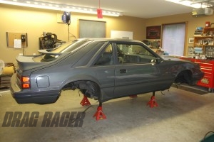 | |||
In the last installment of “War Pony,” we examined the instrument package and suspension components used on the project. Now we’ll take a close look at the brake system along with more of the rear suspension parts, primarily the trailing arms. | |||
Brake Basics | |||
Bringing a race car down from warp speed is huge. Now factor in street driving a car like our War Pony and the brake selection process becomes more complex. The reasons being that you have to deal with constant brake cycles, seriously mismatched front and rear tire sizes and the need for a parking brake. | |||
Brake Rotors | |||
There are a number of different rotors currently in production. For most applications, there are two (possibly three) different types that see regular use: solid steel and iron rotors along with more exotic carbon rotors (carbon doesn’t work for our project). Solid rotors can be manufactured from steel or gray cast iron. Both have their merits, but in the end, a rotor must have good wear and friction properties. It must be rigid and have sufficient strength at high temperatures. Rotors are measured by the outside diameter as well as the total thickness across the pair of contact surfaces. A vented rotor will always be thicker and in most cases, heavier than a solid example. In terms of diameter, the rotor is always limited by the size of the wheel. This is important in most drag race applications, since the majority of wheels are constructed with a 15-inch diameter. | |||
Brake Hats and Hubs | |||
In a high-performance drag race system, the brake rotor is attached to the hat and the hat is attached to either the wheel hub or the axle flange. By design, the hat provides a long path for heat to travel from the brake swept area surface to the wheel bearing. If this pathway is short, then wheel bearings will have an equally short life span. The most common material for hats in aftermarket applications is aluminum alloy. It’s ideal because it’s very light and has the ability to dissipate heat very quickly. Not only does aluminum reduce weight, it reduces the thermal stress upon the rotor. Since aluminum expands at a rate greater than iron or steel, it tends to equalize the expansion difference created by the sometimes-extreme temperature of the rotor. Quality engineered hats take the heat path into consideration during design. This allows the heat to be directed away from the bearings, permitting the wheel, which acts as a huge heat sink, to absorb the temperature. Typically, a quality brake setup will include a single-piece hub/brake hat configuration. Mark Williams notes that by manufacturing a relatively large diameter hub, the rotor size can effectively be reduced. In turn, this reduces the rotating mass (since the weight of the rotor is less). Another consideration when buying a brake kit is the spindle. Many brake kits mandate spindle modifications. For example, the 1987 (and up) Mustang spindles had the OEM brake caliper mounts milled off. We converted our Mustang to a 1987-up-style spindle. This simplified the brake selection process. We shipped the OEM spindles to M-W and they returned them machined to accept their brake package. | |||
Brake Calipers | |||
M-W brake systems rely on upon a robust fixed caliper. Each caliper has a pair of pistons (or a quartet of pistons), arranged from side to side. As fluid pressure is applied, the pistons equally receive pressure and the caliper clamps the rotor. A fixed caliper such as this tends to wear the pads evenly. While it incorporates one (or more) extra seal than a floating caliper (whichmight make it more likely to leak), a fixed caliper will take more hard stops before it overheats. The most important factor is caliper flex. A fixed caliper is usually far more rigid than a floating configuration. Caliper rigidity (and consequently, caliper flex) is hugely important. Mark Williams points out, “The most important characteristic for a caliper’s stopping ability is the bridge strength. The limiting strength factor for calipers of this type (fixed calipers) is the fastener strength. All of the attention over material types (forged or billet) has little effect on the bridge strength. We tested solid one-piece designs but the bolted together caliper [aluminum] was more rigid due to the higher modulus of the steel bolt strength. We use four 7/16-inch diameter fasteners plus a support bushing to eliminate caliper flex.” There are two types of calipers typically used in drag race applications: Two-piston and four-piston calipers units. Two-piston calipers are lighter, but they have less ultimate stopping strength than four-piston designs. In our case, War Pony will likely weigh in the range of 2,800 or so pounds, ready for battle. Due to the street-strip nature of our project, a four-piston caliper is the best bet. The same applies to the rear. | |||
Trailing Arms | |||
| In addition to the braking package on our Mustang, we also modified the rear suspension. A platform such as Fox-body Mustang or a GM G- or A-body (which includes a very similar rear suspension arrangement) comes from the factory with the rearend supported by triangulated trailing arms (typically U-shaped stampings). Boxed replacements are available, but that’s more of a crutch. The real answer is to install tubular components with adjustment capability. | |||
Pinion Angle and Preload | |||
The adjustable upper and lower trailing arms used provide the ability to fine-tune the suspension and to set the static pinion angle. Why is pinion angle so important? If the pinion angle isn’t properly set, the operating angles of the driveshaft and U-joints can’t be controlled. Pinion angle is measured between the pinion gear flange and the driveshaft. As the suspension in a car wraps up, the pinion is driven upward (not good). In order to ensure that the pinion is correctly oriented while under power, it’s typically set nose down static. For most applications with solid rear suspension bushings or spherical bearings (rod ends), the pinion angle should be set between to -1 to -2 degrees (- or minus is negative angle, or pointing “down”). If the suspension incorporates OEM-style rubber suspension bushings, then a pinion angle of -3 to -4 degrees is preferred. The reason is due to the added deflection in rubber bushings. What about preload? Preload is a major tuning tool in traditional drag race 4-link cars, but when it comes to a triangulated 4-link, it’s not quite the same. With a conventional, non-triangulated 4-link (like you’d find in a conventional drag race car setup), you can shorten the upper right bar to increase the preload on the right rear tire. If you lengthen the same bar, then more load is placed on the left rear tire. Sounds easy enough, but it doesn’t work that way with a triangulated 4-link like the one in our Mustang. On cars equipped with triangulated upper control arms setting preload isn’t possible with the upper bars. When one upper control arm is adjusted then you’re actually shifting the rearend housing left or right (depending upon which of the bars you adjust). The folks from TRZ Race Cars point out that the upper bars on a triangulated 4-link are used to center the rearend housing from side to side (by adjusting one upper). The upper bars are also used to set the pinion angle (by adjusting both uppers the same direction and same amount). Adjustable lower bars are used to center the tires front to back in the wheel well and to make minute wheelbase dimensional changes. Then how can you tune or preload the rear suspension in one of these cars? You use an anti-roll bar (ARB). Then adjustable shock absorbers (front and rear), front suspension limiters and to a lesser degree, specific spring rates are used to get the car to hook. | |||
| Rod ends are used for countless purposes in drag racing applications, everything from throttle linkage to suspension hardware depends upon them. For the War Pony project, we use rod ends on the steering assembly (as tie rod ends) and for rear suspension. In any critical application, a high-quality, chrome-moly, three-piece rod end is the way to go. This is what is often referred to as an “aircraft” rod end. Here are the basics of what makes them good. The Teflon Mix: In a racing application, rod ends with Teflon inserts work perfectly, particularly where you cannot lubricate a rod end. Teflon liners are made up with a carrier component, most often a fabric that provides compressive strength while a Teflon component provides the lubricity. (It’s all held together with a mix of bonding resins.) The Teflon liner and the race are bonded together, and due to this, the rod end ball rides on the liner. As the ball rotates, Teflon is rubbed onto the surface, hence the lubrication. Typically two- or three-piece rod ends are available with Teflon liners. Not all manufacturers use the same materials; some cut corners by using what is called virgin Teflon. Virgin Teflon tends to be relatively soft (approximately 10,000 pounds psi compressive strength). In comparison, a high-quality composite Teflon liner will have a compressive strength of somewhere between 40,000 and 60,000 psi. A rod end with a quality Teflon liner will also have a tighter fit. That’s due to the fact that excess clearance between the ball and the race is eliminated. Adding a Teflon liner to a rod end doesn’t necessarily mean it’s a quality piece. Consider the case of rod ends “beating out,” which is really two problems. The first involves the deformation of low-strength, self-lubricating liners. Many cheap rod ends are manufactured with races constructed from molded plastic (in some cases the plastic is mixed with a fiberglass filler). To provide some lubrication, a small amount of Teflon might be added. Because of the ingredient mix, these low-buck rod ends typically have a compressive strength of no more than 15,000 psi. Due to the poor compression strength, the race will deform long before the body sees any damage. Aside from MIL specs for Teflon-lined bearings, there are no standards set for liner bond strength. Because of this, it’s buyer beware. Material Matters: Teflon isn’t the only important material choice. The spheres or balls of the rod end are most often subjected to the highest loads the rod end encounters. Due to the high loading, the balls must have the greatest hardness along with the greatest ultimate strength. Quality rod ends are built with heat-treated steel balls (including balls made from stainless steels, chrome-moly steels and 52100 bearing steels). The balls must be extremely hard in order to remain round. (Additionally, the rod end balls are often chrome plated to provide a smooth bearing surface.) The hardness of the ball along with the ball’s capability to remain round is absolutely critical in use. The race must also be hard, but not to the level of the ball. The majority of three-piece rod ends incorporate a race manufactured from through-hardened steel alloy or from a stainless steel that can be hardened. In either case, the outer races are heat treated for both strength and wear resistance. “Econo” rod ends regularly have bodies that are built from low carbon mild steels. It’s not possible to through-harden this material. Although an inexpensive material such as low carbon steel might work in a lightly loaded application, you’ll find that a rod end body manufactured from chrome-moly steel or heat-treated stainless steel is a better choice for severe duty applications. It’s difficult to beat a high quality heat-treated steel body rod end when it comes to ultimate rod end material strength. | |||
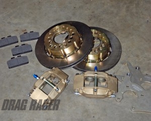 Photo 1 shows the complete brake package we’re using. The front brake system is a four-piston caliper and a solid rotor combination, while the rear is an M-W Pro Street package, which includes a four-piston caliper along with a vented rotor. Not shown is a single-piston mechanical caliper. Photo 1 shows the complete brake package we’re using. The front brake system is a four-piston caliper and a solid rotor combination, while the rear is an M-W Pro Street package, which includes a four-piston caliper along with a vented rotor. Not shown is a single-piston mechanical caliper.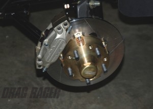 Photo 2 shows the front brake package installed. Photo 2 shows the front brake package installed. | |||
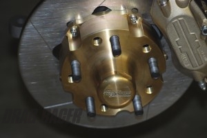 The front hubs are double drilled for 4.5- and 4.75-inch wheel bolt patterns. Race-style long screw-in wheel studs for the front in a 1/2-inch diameter are included. The rotor is attached to the hub by way of cap screws (bolts). When cap screws are used (shown here) the hat must be designed to be relatively thin and flexible. It must also be designed to work without breaking. The reason for this is expansion. The hat must expand with the rotor as it builds heat. The front hubs are double drilled for 4.5- and 4.75-inch wheel bolt patterns. Race-style long screw-in wheel studs for the front in a 1/2-inch diameter are included. The rotor is attached to the hub by way of cap screws (bolts). When cap screws are used (shown here) the hat must be designed to be relatively thin and flexible. It must also be designed to work without breaking. The reason for this is expansion. The hat must expand with the rotor as it builds heat.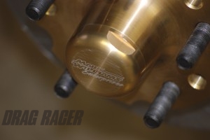 In Photo 4, the billet aluminum dust caps are fitted to the front brakes. The caps screw on and seal with O-rings. Behind the dust caps are high-end Timken bearings and a CR seal. In Photo 4, the billet aluminum dust caps are fitted to the front brakes. The caps screw on and seal with O-rings. Behind the dust caps are high-end Timken bearings and a CR seal. | |||
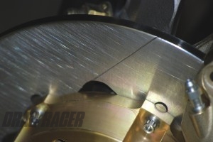 The steel brake rotors are grooved to provide a path for brake pad dust. In other race applications, slots are used to eliminate gas buildup between the rotor and the brake pad, but this is seldom an issue in a drag racing. The steel brake rotors are grooved to provide a path for brake pad dust. In other race applications, slots are used to eliminate gas buildup between the rotor and the brake pad, but this is seldom an issue in a drag racing. 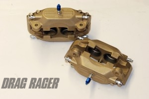 Most race and high-performance calipers are a fixed design. In this system, the caliper has a pair of pistons equally arranged from side to side. As fluid pressure is applied, the pistons equally receive pressure and the caliper clamps the rotor. Most race and high-performance calipers are a fixed design. In this system, the caliper has a pair of pistons equally arranged from side to side. As fluid pressure is applied, the pistons equally receive pressure and the caliper clamps the rotor. | |||
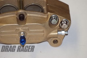 One of the most important aspects of caliper design is bridge strength. If the caliper flexes, it can’t apply consistent pressure to the pad, and in turn, to the rotor. In this caliper, four 7/16-inch-diameter fasteners are incorporated along with a support bushing to eliminate caliper flex. Additionally, the use of four screws allows the caliper to be somewhat universal, left or right. It also allows you to effectively bleed each side of the caliper. One of the most important aspects of caliper design is bridge strength. If the caliper flexes, it can’t apply consistent pressure to the pad, and in turn, to the rotor. In this caliper, four 7/16-inch-diameter fasteners are incorporated along with a support bushing to eliminate caliper flex. Additionally, the use of four screws allows the caliper to be somewhat universal, left or right. It also allows you to effectively bleed each side of the caliper.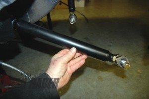 The lower trailing arms used are from TRZ. The lower bar adjustment shown is designed to set the wheelbase on the car and can also be used to center the wheels in the wheel wells. This setup allows for minute wheelbase changes. The lower trailing arms used are from TRZ. The lower bar adjustment shown is designed to set the wheelbase on the car and can also be used to center the wheels in the wheel wells. This setup allows for minute wheelbase changes. | |||
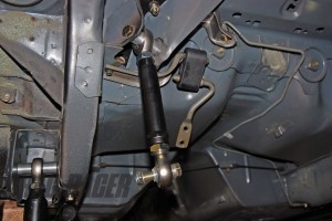 In the case of a car like our War Pony, which features stock-style triangulated suspension, the upper bars are used to center the rearend housing from side to side (by adjusting one upper). The upper bars also used to set the pinion angle by adjusting both uppers the same direction and same amount In the case of a car like our War Pony, which features stock-style triangulated suspension, the upper bars are used to center the rearend housing from side to side (by adjusting one upper). The upper bars also used to set the pinion angle by adjusting both uppers the same direction and same amount 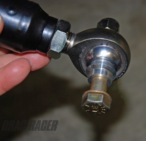 The bottom bar is set up to accept a large 3/4-inch rod end. The rod end is a three-piece aircraft-style unit, manufactured from chrome-moly with a self-lubricating Teflon liner. This is a massive, high strength bearing, capable of withstanding far more than we can ever dish out with our project car. The bottom bar is set up to accept a large 3/4-inch rod end. The rod end is a three-piece aircraft-style unit, manufactured from chrome-moly with a self-lubricating Teflon liner. This is a massive, high strength bearing, capable of withstanding far more than we can ever dish out with our project car. | |||
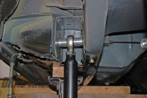 At the body side, both upper and lower trailing arms use machined spacers to fit the rod ends into the stock Mustang suspension pockets. TRZ manufactures these billet aluminum spacers and provides them with their trailing arm components. At the body side, both upper and lower trailing arms use machined spacers to fit the rod ends into the stock Mustang suspension pockets. TRZ manufactures these billet aluminum spacers and provides them with their trailing arm components.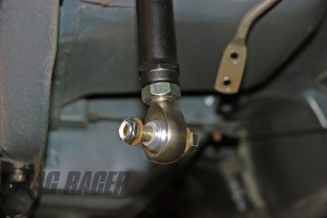 The upper trailing arm for our application does not incorporate a spacer on the housing side. The TRZ-fabricated housing we’re using is designed like a conventional 4-link (complete with three sets of mounting holes per side on the top). Each bar has a built in hex for easy adjustment. The upper trailing arm for our application does not incorporate a spacer on the housing side. The TRZ-fabricated housing we’re using is designed like a conventional 4-link (complete with three sets of mounting holes per side on the top). Each bar has a built in hex for easy adjustment. | |||
| |||